CR-La60 Aiwa Diagrama Electrico: Comprehensive Guide
The cr-la60 aiwa diagrama electrico is a vital resource for understanding the inner workings of the AIWA CR-LA60 audio device. For professionals and enthusiasts alike, having access to a detailed electrical diagram can simplify troubleshooting, repairs, and upgrades. In this article, we delve into the essential components, layout, and practical applications of this diagram, providing you with all the information needed to master its use.
What Is the CR-LA60 AIWA Diagrama Eléctrico?
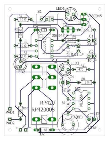
The CR-LA60 AIWA diagrama eléctrico is a schematic representation of the electronic components and circuitry within the AIWA CR-LA60 device. This diagram provides an in-depth look at how the device’s circuits are connected, including pathways for power, audio signals, and control mechanisms. By analyzing the diagram, users can pinpoint faults, understand the device’s functionality, and perform effective repairs.
The CR-LA60 model is known for its compact design, high-quality audio output, and advanced electronic systems. The electrical diagram serves as the blueprint for its operation, ensuring technicians and hobbyists can efficiently maintain or modify the device.
Key Components in the CR-LA60 AIWA Diagrama Eléctrico
1. Power Supply Circuit
The power supply circuit is a critical part of the CR-LA60. It includes:
- Transformer: Steps down the voltage for the internal circuits.
- Rectifier: Converts AC power into DC.
- Capacitors: Smooth out voltage fluctuations to ensure a stable power supply.
Understanding this section of the diagram is essential for diagnosing power-related issues such as the device failing to turn on or inconsistent performance.
2. Audio Signal Pathways
This section showcases the journey of audio signals through the device:
- Input Stage: Receives signals from external sources.
- Amplifiers: Boosts audio signals to deliver high-quality sound output.
- Filters: Removes noise and ensures clean audio performance.
Troubleshooting poor audio quality often begins with examining the pathways detailed in the diagram.
3. Control Circuits
Control circuits manage the device’s functionality, including:
- Volume Controls: Potentiometers that adjust the sound level.
- Tuning Mechanisms: Components responsible for precise frequency selection.
- Microcontroller Units (MCU): Facilitate advanced features like presets and digital tuning.
How to Use the CR-LA60 AIWA Diagrama Eléctrico for Repairs
Step 1: Identify the Fault
Using the diagram, locate the area of the device experiencing issues. For example, if there’s no sound, focus on the audio amplifier and speaker connections.
Step 2: Test Components
Refer to the diagram to understand the connections and test individual components, such as resistors, transistors, and capacitors. Use a multimeter to measure continuity and voltage.
Step 3: Replace or Repair
Once the faulty component is identified, replace or repair it using the specifications from the diagram. Ensure compatibility to avoid further damage.
Benefits of the CR-LA60 AIWA Diagrama Eléctrico
1. Streamlined Troubleshooting
The detailed schematics eliminate guesswork, allowing technicians to quickly identify faults and resolve them.
2. Enhanced Understanding
For hobbyists, studying the diagram enhances knowledge about electronic circuits and their interactions within a device.
3. Cost Savings
Repairing the device yourself using the diagram saves money compared to professional servicing.
Common Issues Solved with the CR-LA60 AIWA Diagrama Eléctrico
1. Power Failures
By analyzing the power supply section, users can diagnose issues like blown fuses, faulty transformers, or failed rectifiers.
2. Audio Distortion
The audio pathways in the diagram help identify issues such as damaged capacitors or resistors that may cause noise or distortion.
3. Tuning Problems
Control circuit schematics enable users to troubleshoot and repair tuning-related faults, such as stuck dials or misaligned presets.
Tips for Interpreting the Diagram
- Familiarize Yourself with Symbols: The diagram uses standardized symbols for components like diodes, resistors, and capacitors. A reference guide can be helpful.
- Follow the Flow: Trace the connections step by step to understand how signals and power travel through the device.
- Use Proper Tools: A magnifying glass, multimeter, and soldering tools are invaluable for working with intricate circuits.
Where to Access the CR-LA60 AIWA Diagrama Eléctrico
You can find the CR-LA60 AIWA diagrama eléctrico in the device’s service manual, available through AIWA’s official website or third-party repair forums. Ensure the source is credible to avoid using outdated or incorrect schematics.
Advanced Insights into the CR-LA60 AIWA Diagrama Eléctrico
4. Signal Processing and Noise Reduction
The CR-LA60 AIWA diagrama eléctrico also highlights the device’s advanced signal processing capabilities. This includes:
- Noise Suppression Circuits: These are responsible for minimizing background noise, ensuring clear audio output. Look for the integration of capacitors and inductors near the input stage in the diagram.
- Equalization Components: These circuits enhance sound frequencies to deliver a balanced audio experience. Pay close attention to resistors and operational amplifiers dedicated to fine-tuning audio performance.
- Digital Signal Processor (DSP): In modern versions of the CR-LA60, a DSP may be included to manage audio fidelity digitally, reducing distortion and enhancing clarity.
Understanding these aspects is particularly useful for optimizing audio quality or customizing the device to meet specific preferences.
Protection Circuits for Device Longevity
The CR-LA60 includes several protective measures, all mapped out in the diagram:
- Overload Protection: Protects the device from excessive current draw, often achieved using fuses or thermal cutoff switches.
- Surge Protection: Varistors and diodes protect against voltage spikes.
- Short Circuit Prevention: Components like shunt resistors ensure the device does not sustain damage in case of accidental short circuits.
When performing repairs, always ensure these protective measures are intact to maintain the longevity of your device.
How to Adapt and Modify Using the Diagram
The CR-LA60 AIWA diagrama eléctrico is not just for repairs—it can also serve as a guide for modifications. Here are a few possibilities:
Adding Auxiliary Input
The diagram can help locate the existing input circuits and guide the addition of an auxiliary port. This allows for modern connectivity options such as smartphones or Bluetooth receivers.
Upgrading Components
By referencing the specifications on the diagram, you can replace outdated components with modern equivalents, improving performance and efficiency. For instance:
- Upgrade capacitors to high-quality electrolytic versions for better sound clarity.
- Replace transistors with low-noise variants to reduce distortion.
Customization of Audio Profiles
Tinker with equalization settings or add custom filters to achieve a personalized audio output. Use the diagram to locate adjustable resistors or control ICs.
Challenges in Using the Diagram
While the CR-LA60 AIWA diagrama eléctrico is an invaluable tool, it can pose challenges for beginners:
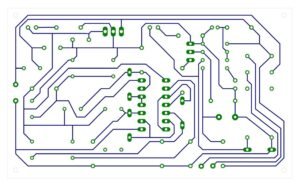
- Complex Layouts: The dense arrangement of components and connections may seem overwhelming. Break the diagram into smaller sections to study incrementally.
- Obsolete Components: Some parts listed in the diagram may no longer be available. Use the diagram to identify suitable substitutes.
- Interpreting Symbols: A lack of familiarity with schematic symbols can hinder progress. Consider using online resources or guides for reference.
Resources for Further Learning
To fully utilize the CR-LA60 AIWA diagrama eléctrico, expanding your knowledge of electronics is essential. Here are some recommended steps:
- Take Online Courses: Platforms like Coursera and Udemy offer courses on electronics and circuit analysis.
- Join Communities: Forums such as DIY Audio and Electronics Stack Exchange are excellent places to seek advice and share experiences.
- Use Simulation Software: Tools like LTSpice or TINA-TI allow you to simulate circuits before working on the actual device.
Conclusion: The Importance of the CR-LA60 AIWA Diagrama Eléctrico
The CR-LA60 AIWA diagrama eléctrico is more than just a repair manual—it’s a comprehensive guide that empowers users to understand, troubleshoot, and innovate with their devices. From fixing common issues to customizing the device’s functionality, this schematic is an indispensable resource for technicians and enthusiasts.
By studying the diagram and applying the insights shared in this guide, you can ensure your CR-LA60 delivers optimal performance for years to come. Whether you are repairing, modifying, or simply exploring the device’s design, the electrical diagram will be your trusted companion.